
- Step 1
Select the chassis and architecture.
Confirm the physical car before opening its geometry record. Select the suspension architecture that matches the car; the front reference example uses independent double-wishbone / SLA suspension.
Before moving on: The selected record belongs to the car being measured, not simply another car with the same number. - Step 2
Define your measurement references.
Use the chassis datum, centerline, units, and axis directions displayed in the app. Measure from those same references for every point. Write down how the physical reference was established so the crew can repeat it.
Before moving on: A left-side point, front or rear offset, and height all use the intended signs and units. - Step 3
Enter and check the mapped points.
Record the required suspension and chassis point locations, including the current mount configuration. Use the front, side, top, and 3D references to check where the entered points appear.
Before moving on: The required points are complete and the drawing matches their expected side and location. - Step 4
Save the baseline and calculate.
Save the measured geometry. Use the calculation appropriate to the selected model. For ride-height analysis, enter LF, RF, LR, and RR frame heights at the mapped chassis stations and use Calculate at Ride Height, or select baseline heights.
Before moving on: The calculation uses the intended mount state and heights. Do not overwrite the baseline with a temporary modeled position. - Step 5
Check optional calculation inputs.
The front reference screen has wheelbase, CG height, and front brake percentage fields. Anti-dive needs those values. Use established measurements or references, and leave unavailable values unset.
Before moving on: The required values are known; an empty field has not been replaced with a guess to obtain a result. - Step 6
Repeat the measurement when inspecting the car.
After an impact or suspected movement, measure the same point from the same references and compare it with the saved baseline. Investigate measurement differences before treating them as proof of chassis movement.
Before moving on: The original baseline is retained and any new measurement can be traced to the inspection.
Tech Center / Geometry
Geometry: establish the chassis reference.
Start with the physical chassis and a consistent measurement system. Calculated geometry is only as useful as the point locations you enter.
App reference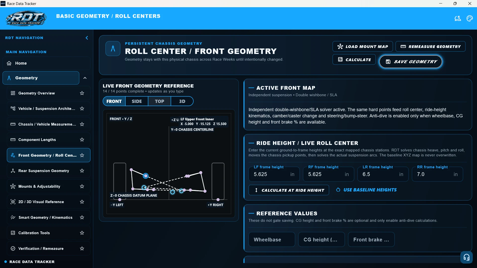
Worked workflow
Measure and save the chassis hard points in the shop. At a different ride height, enter the current frame heights and review the live calculation while retaining the original map. If a mount is later suspected to have moved, remeasure that location from the same physical references.
Common mistakes to avoid
- Mixing inches and millimeters or changing the datum midway through mapping.
- Swapping left and right, reversing an axis, or entering a point on the wrong side of the centerline.
- Using incomplete or guessed inputs and treating the result as a measured fact.
- Replacing the baseline simply to make a discrepancy disappear.